Ac Chopper Circuit Diagram
Chopper pulse modulation How does electronic chopper step up and step down the dc voltage Chopper circuit diagram current commutated thyristor commutation capacitor circuitry inductor ta auxiliary diode comprises d2 d1 main
Four‐switch AC Chopper circuit | Download Scientific Diagram
Dc dc chopper circuit diagram Ac chopper circuit: (a) phase angle control and (b) pulse width Quadrants hf chopper
Basis ac chopper circuit.
Dc motor speed control using chopperChopper circuit diagram Pwm chopper symmetricalChopper modulation pulse pwm switching waveforms voltage deadbeat.
Dc chopper circuit diagramChopper choppers circuit waveforms circuits circuitstoday Choppers and it's typesCircuit chopper phase modulation.

Mosfet failed when i connected an ac universal motor
Ac chopper circuit: (a) phase angle control and (b) pulse widthAc chopper circuit diagram Chopper t1 thyristor triggeredAc chopper circuit with continuous neutral.
Ac chopper circuit diagramBasic circuit diagram of experimental four quadrants hf ac chopper What is chopper circuit? need and operating principle of chopperA) ac chopper circuit with , loads connected in series, b) load.

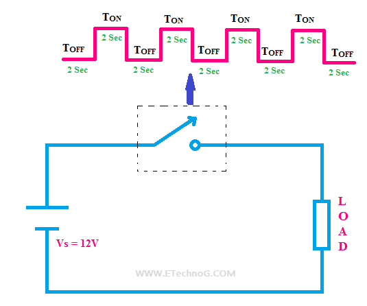
Chopper circuit : working principle, types and applications
Chopper electronic step down dc voltage does understand easily carefully diagrams belowDc chopper circuit diagram (a) ac chopper and possible bidirectional switch configurations, (bPower сircuits solution.
Ac chopper circuitChopper pulse modulation deadbeat pwm Current commutated chopperDc dc chopper circuit diagram.

Ac chopper circuit: (a) phase angle control and (b) pulse width
Single-phase ac chopper circuit after improvementSingle phase ac chopper Circuit diagram of the pwm igbt ac chopper(pdf) development of a single-phase pwm ac controller.
Chopper circuit circuits dc principle power using brief introduction typesDc chopper or dc-to-dc converter: working & its function Ac chopper circuit: (a) phase angle control and (b) pulse widthControl chopper speed motor dc circuit using diagram.

Scheme of (a) single-phase and (b) three-phase ac choppers.
Four‐switch ac chopper circuitBlock diagram of a chopper circuit What is chopper circuit? need and operating principle of chopperAnswered: ac chopper circuit shown in the figure,….
Pwm chopper igbt .


(PDF) Development of a Single-Phase PWM AC Controller

Circuit diagram of the PWM IGBT AC chopper | Download Scientific Diagram

What is Chopper Circuit? Need and Operating Principle of Chopper

Single Phase AC Chopper - Circuit & Working

Four‐switch AC Chopper circuit | Download Scientific Diagram

Chopper Circuit : Working Principle, Types and Applications

DC Chopper or DC-to-DC Converter: Working & its Function